
WildCat FM /technical station. attic of station's chief /Top floor /White Room FM stereo matrix generator /5 
Production is advanced with Step by step with the verification of each circuit.
The following measuring instruments are necessary to
verify FMmodulator explained on this page experimenting.
The power supply of this experimental circuit
uses a good quality about single power supply of 12V/100 mA in capacity. FM stereo modulation signal Spectrum seen from side of electric wave
The spectrum analyzer (electric wave analysis device) is used to see the electric wave
(frequency axis side) directly. The appearance of the electric wave itself can be seen
directly by using the spectrum analyzer.
The image below is a spectrum of the modulated electric wave the pilot signal of the produced experiment modulator.
A clean pilot signal also : as long as it sees with the oscilloscope (time axis).
When the state recorded in the electric wave is seen, the thing that in the
pilot signal, there is a little distortion is understood.
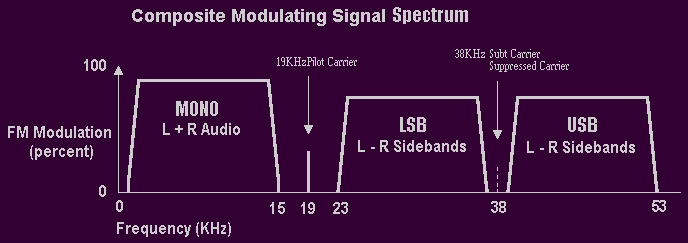
19KHz parts from a basic wave and the main body of the pilot signal.
38KHz parts and the garbage of the pilot signal that the second high
note wave and 57KHz part and the modulator puts out the third high note wave below.
However, it is a to tell the truth tolerable because of about -60dBm the third high note
wave of 57KHz state of the signal.
Image in state to turn off pilot signal continuously
When the pilot signal is turned off, the subcarrier of 38KHz is confirmed.
it is not, and the thing completely suppressed leaks to the
subcarrier of 38KHz slightly when there is no audio signal though it
is originally in the state of suppression. it is possible to observe
it clearly by seeing the residual subcarrier at 0.2KHz Deviation
level with spectrum analyzer in the high frequency in a straight line detector.
Shall I assume it is good because it clears the standard enough because it is about -60dBm
For career suppression of the subcarrier of 38KHzThe following
standards exist in "Quality of the electric wave in the frequency modulation broadcasting" of Radio Law.
+/- 75KHz of Frequency Deviation level 1% of cycle of main signal carrier by
remaining of subcarrier on inside
Frequency Deviation +/- 0.75KHz following measured when Frequency Deviation of a
main signal carrier who happens because of the leakage of the subcarrier of 38KHz
turns off the pilot signal by 1% or less for +/- 75KHz are things, and the suppression
of the sub career of 38KHz becomes -40 a dB at 1%. The subcarrier is observed to remain
in 0.75KHz-40dBm place even if it sees with Spectrum analyzer in the high frequency.
The following put and verify the audio signal.
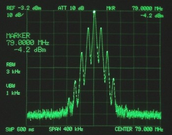
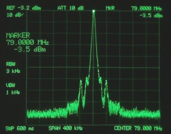
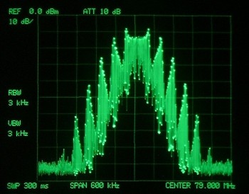
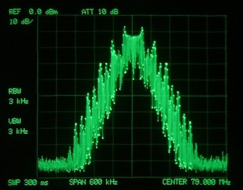
Pilot OFF and the right side are on a pilot images. a left image
The modulation level is set as 100%(cycle 150kHz Frequency Deviation) at
this point, and measured similarly thereafter.
The subcarrier of 38KHz understands, and suppression understands being
confirmed and dynamically and it is understood to be deteriorated though
it is necessary to suppress the subcarrier for L+R left image basically.
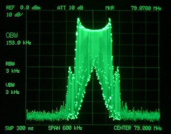
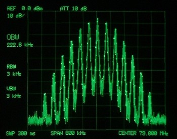
The occupation band extends because the subcarrier stands up when the signal enters one side channel
if subcarrier (DSB/double-sideband) signal measures 100% standing up
occupation band, it becomes an occupation of 222.6KHz by the DSB signal of
left Pilot off if the opposite phase signal is put though the setting of the
modulation level 100% of L+R (cycle 150kHz Frequency Deviation) has not been changed.
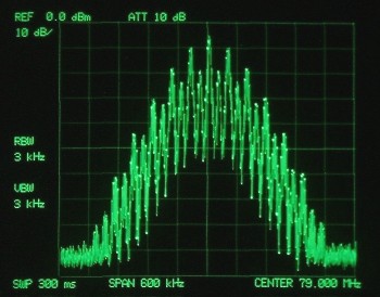
When the complete do balance of Balanced modulator When FM tuner is monaural, the
sound is not emitted even if this signal is received. (suppression of about - 60dB)
Modulation by music signal
For maximum Frequency Deviation of a main signal carrier The
following standards exist in "Standard how to transmit the frequency
modulation broadcasting" of Radio Law.
maximum Frequency Deviation :+/- 75KHz
As for the transmission of FM, the known range where it turns over and
Deviation can do because they are the Frequency number modulations is restricted.
it is a translation called the width of the shake +/- 75KHz (150KHz).
"it is best and paddle sound" will have gone out at this time by the
translation that the range to make the frequency of the sent electric wave
change says 150KHz (100% modulation) in the maximum, and it becomes all standards.
However, it is not a simple story because there is a big difference in
the volume received by the quality of the signal even by the same
several 150KHz Frequency Deviation by the difference of the transmitter.
it is a current state because it doesn't correctly understand this standard to
our regret as for the mini FM station to have emitted the sound vaguely. if the
modulation level seen from the electric wave is not correctly done as for the
mini FM station that boasts of the ownership of an expensive audio processor or
the Compressor limiter, to free of the expensive apparatus the decoration regrettable.
This time, the electric wave of the signal modulated in shape to actually use the experiment modulator is seen.
The processor (Compressor/limiter) is connected with the former steps of the
experiment modulator naturally, the voice input of the modulator is
adjusted with the limiter, and it is adjusted to the modulation level 100%
(150KHz Frequency Deviation ). This adjustment inputs the music signal it
is not in a continuous signal but with the change and should adjust the
limiter point within the range of the multiplication 150kHz at time.
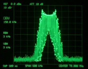
Deviation or less moving catches by using the peak holding function of Spectrum analyzer
After the peak is held and the music signal is thrown for several minutes,
occupation band (OBW) is measured.
if the processor for FM Broadcast is correctly adjusted, it is possible to
adjust it as possible to be maintained to the modulation level 100% (150kHz Frequency Deviation) correct.
However, BEHRINGER DSP9024 etc. are a standard mastering processors of the mini FM station,
and, then, the occupation band cannot be maintained for FM Broadcast as long as neither the
emphasis loop back nor Pre-emphasis, etc. are processed because it is not. it is
necessary to note it for the maintenance of the modulation level because a moderate device is needed.
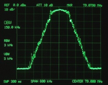
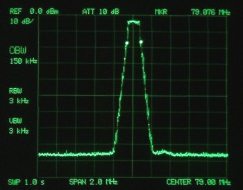
The measuring span was seen measuring it with 600KHz and 2MHz.
Even if modulation Spectrum is seen, it is sideband spurious few, extremely clean,
and the occupation band is also narrow because experiment matrix modulation
circuit has synthesized Pure signal unlimitedly from the beginning.
What is the optimization of FM voice signal of recent said well ?
There is not emitting a strapping sound from FM transmitter in the
optimization of the sound, and , mini component and departure other party
of the radio-cassette of the "Paddle sound" moderate on t compresses it as
it deviates from the frequency occupation band of 150kHz and the sound is extreme.
The optimization of FM voice signal in the state to disregard the occupation band of 150
kHz that are the modulation level 100% is not possible.
There is no meaning at all if neither sound making nor the voice processing
process of the processor is constructed and optimized with these 150kHz occupation bands (OBW) maintained.
However, the commercial broadcast bureau with the occupation band maintained cannot remainder
achieve the voice level output with mini FM transmitter being marketed
now because the frequency occupation band diffuses by badness and spurious the MPX signal
purity even if the audio signal very optimized is put and it wastes the band greatly.
Even if the same audio signal that the optimization processing is done as the
commercial broadcast bureau is input, it causes it by the signal with inferior loss of 6dB or12dB.
Harmful spurious and obstruction filter that modulator puts out
This time, to obstruct spurious that the produced experiment
modulator is harmful, the filter circuit was united to the output circuit.
OP AMP two negligent filter steps
and the circuit that uses L
is actually .
necessary to obstruct Side spurious and
this assume it is good because it is experiment this time.
The following standards exist in "Standard how to transmit the frequency
modulation broadcasting" of Radio Law.
I think that it can understand the thing that is obviously strict
prohibition to spurious of higher-order when the maximum value of the
voice modulation frequency sees signal Spectrum.
The band is greatly wasted by spurious that happens due to the distortion
of the MPX signal because FM is a frequency modulation though it is a
thing why spurious is strict prohibition. Because the band is wasted, the voice level is not raised.
FM stereo modulator has various methods. The generation origin of
modulation spurious is also various depending on the method.
Because the modulator of the matrix method made on this page promotes
the MPX signal based on the sine wave signal, spurious of a synthetic
signal is extremely few as long as the thing of the saturation of the circuit etc. is not done.
The signal is time-sharing cut digitally for the modulator of the SW method, the prototype of sub career
(DSB) signal is produced, and it builds in a clean MPX signal by the filtering processing afterwards
because harmful spurious is contained voluminously at this point. The electric wave is modulated if the filtering
processing is not properly done by harmful spurious and the band is diffused.
The filtering processing is an important problem because the diffusion of the band causes extreme tone quality
deterioration also on the reception side.
FM modulator of a full, digital method that is becoming a main current to use
DSP is not unexpectedly known modulation spurious that the generated digital noise
is harmful is output at the digital-to-analog conversion recently.
The filtering processing to the output circuit of optimod 8100 of the matrix method
To spurious a digital noise when the output circuit of latest digital processor
optimod 8400 is seen, extreme filtering processing repeats and is given by LC though
doesn't give.
However, full, digital FM modulator that must be normally high sound quality.
Story that it is strange to cause signal deterioration by digital noise generated from D/A converter?..
it is extreme filtering processing and a vicious circle of the tone quality deterioration
it is possible to visit importance for modulation spurious from this thing.
Experiment Matrix modulator Wild_mod.Ver-1 /beta
How though it was experiment who advanced production with
Step by step with the verification of each circuit ?
I think that the performance one is understood if each measurement result can be seen.
Normally, do though it might be place what that means specs here writing and even very?
Please evaluate it more suitable making for the sound. Please making for the spec must measure oneself and verify it.
The circuit chart open to the public here produces, remodels, modifies, deteriorates the
circuit as long as it privately enjoys it, and freely.
All circuit chart is temporarily opened to the public as a "bata version."
The above-mentioned and WildCat FM BrodCast technical Factory own the
writing of the open to the public circuit. The reprint and the link of without permission are
prohibited even if any thing and existing.
There is no previous notice for the improvement and the change will
be added to the circuit in the future. The changed circuit chart is renewed at the right time.
Even a small thing : the report to there began to be looking by all means about the
improvement in the basic circuit part etc. in production. A new improvement from
which our Staff is not thought will write "Modified.xxx" in the proposal of will
prosperity in the circuit immediately with the circuit chart change with the
respect in appreciation for obedience, and makes it assume the community ownership
of writing. it is not in the fake camouflaged in the religion, and a truly good
sound is requested, and everyone doesn't do and it wishes the thing that the
circuit of this generator evolves by the technology and the idea...!
Even if the explosion or the accident such as blazing up happens,
your brain cell cannot be concerned of WildCat FM according to the example at all.
Moreover, it doesn't hear of the complaint such as being not able to
reproduce the signal that came near to an individual technology and was
published in the page at all in the thing that the signal obtained from
the open to the public circuit is measured to the origin of an accurate
measurement environment the signal image published in the page. I hope
all in an individual judgment and the self-responsibility. Support to aiming at study and the experiment and the research is not regretted.
Content of page and Q&A for circuit
FM stereo matrix generator introduction
document of yamamoto by WildCat FM |
| jumps to top page. | returns on the previous page. | returns to first page. | returns to Menu page. |
2005/06/01 last modified on 2005/09/20
 |
