
WildCat FM /technical station. attic of station's chief /Top floor /White Room FM stereo matrix generator /3 
Can the operation of the circuit be understood though production is advanced
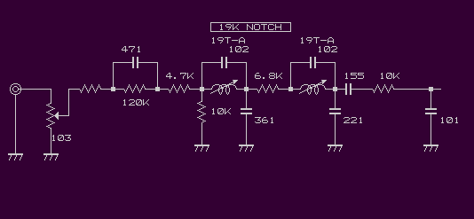
Production of Pre-emphasis /input filter/buffer amplifier circuit
Well,
This circuit attacks the filter part of the voice input. An absolutely necessary
by all means circuit doesn't include the filter circuit of this though it is a
fellow for FM modulator by a so-called MPX filter.
it is necessary to control the upper bound of the voice frequency in some shape within 15000Hz.
it saw making it in feelings this time, and to avoid the interference with the
stereo, the pilot signal, and the audio signal, the purpose of this filter is put.
There is basically a problem in another part actually though it is said as the audio signal
and the pilot signal interfere if this filter doesn't exist, the stereo indicator is blinking,
and the modulation level is not raised and it is likely to lead to a little problem evasion
between a lot of mini FM station. The pilot signal of the modulation part of the transmitter
for mini FM sets up the audio signal easily with the interference with higher-order because
the signal purity is low and the problem happens. The signal generator hardly obstructs an
original pilot signal directly in a usual audio signal (CD or MD etc.) as long as it doesn't use it, too.
In a standard FM modulator even if there is no filter
The thing that the indicator is blinking is not in the overmodulation
level of about 200% either.
Because it is a place that relates to the filter, the easy explanation of the causal relation,
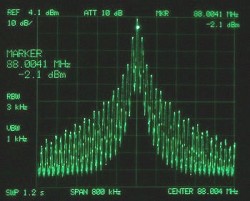
pilot signal and band spurious of general "Toy transmitter" (800KHz span +/-400KHz)
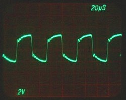
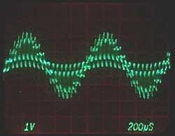
Subcarrier signal of general "Toy transmitter" (MPX signal)(AF_signal /1KHz)
The mutual interference of the harmonic component happens because the subcarrier has been distorted, too though the subcarrier stands up by the voice input. it is correct and the audio signal is incommunicable in the vicious circle of the diffusion of the band in case of it is because the subcarrier has been distorted.of general "Toy transmitter" (MPX signal)(AF_signal /1KHz)
it interferes and it huge spurious to voice region diffuses each other physical the harmonic
component the signal generated higher-order mutually though generated only in higher-order
(The thing which the frequency is low and near also sets off a vicious cycle). In the worst
case, it is likely to hear of the interference beat sound depending on spurious of the pilot
signal in the state of a no sound.
it interferes violently between spurious and the voice signal diffusing of this and an original
pilot signal is obstructed. The tuner received because the pilot signal that the signal purity
is bad cannot originally identify the signal, and causes the blink of the stereo indicator
easily.
The pilot signal should be a sine wave originally signal.
Is the explanation strange ?
it seems to be hardly significant even if this filter is put as long as a basic part
is not improved.
An enough characteristic is obtained by one step by uniting two steps
this time. I also go from making also by and see ?
it is necessary to resonate and because the attenuation characteristic
is obtained, to adjust it. The signal of 19KHz is put from the signal
generator in the voice input, the core is adjusted alternately
several times for the turning attenuation point, and it matches it to the maximum attenuation point.
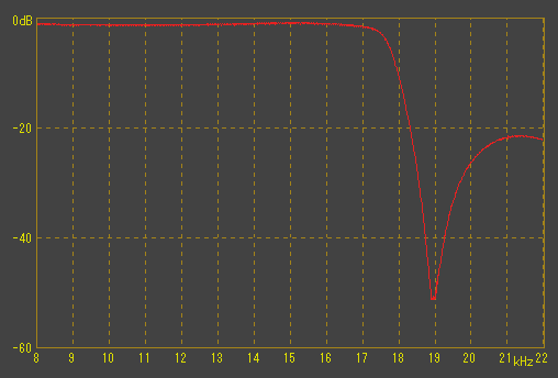
frequency response with of a filter single goods and it saw.
In a filter single goods, limited characteristic it is not a
good thing as the audio circuit that the OP amplifier is easily
multi used and increases the number of extra, active elements that can
be called having a considerably troublesome part in the problem of
the circuit impedance when Pre-emphasis twines though canceled when
the buffer with the OP amplifier is put to evade this.
The influence comes out in the frequency response in a selfish place where the agreement
is put whereabouts, and the change in tone quality takes place. The characteristic
became in Pre-emphasis and the filter's crowding became bitter feeling because it
thought about the thing used by separating Pre-emphasis this time though an integrated
characteristic excellent when "match technique" that went out was used was obtained.
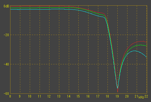
Attenuation characteristic of filter and Pre-emphasis error margin in high region
Because FM straight line detector (ando/RDA-203) had the De-emphasis
ideal characteristic of 50Ęs and 75Ęs, the following characteristics were taken.
Pre-emphasis /OFF to De-emphasis /OFF (RDA-203)
Mutually, the error margin in the state characteristic and Pre-emphasis in the
through state of it as for the emphasis/to pass De-emphasis has been installed on 0.5dB or less.
SONY SA5-ES used as a reference tuner of FM also has little difference between SA5-ES
and (ando/RDA-203) for the characteristic of De-emphasis though took the characteristic.
This time, thing I see with the De-emphasis characteristic of the ideal as a
reference tuner though the difference of about 10dB is seen with 21KHz because SA5-ES
has the high region filter of 19KHz or more though first (SONY SA5-ES) and (ando/RDA-203) were compared.
Homework in the thing though it is anxious that the corner of attenuation is
sweet whether the characteristic of the extent that can be used is made of
securing though the story wandered a little it is Ne though is anxious and
is not possible to know because it sees in the graph of a linear characteristic.
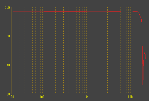
it becomes feeling in the figure below if it sees in the log graph where a
usual audio characteristic is displayed.
It puts it from the overall viewpoint in (10Hz-15000Hz +/- 0.5dB) or less I want to put it in (+/- 0.1dB or +/- 0.2dB)
or less if it sees audio and severely though it is settled. Experiment is done this time.
To catch the frequency response of the emphasis and the filter
If there are a low frequency transmitter and VTVM, the characteristic
can be confirmed though time hangs. it only has to correct the
voltage by the spot frequency according to the table of the
measurement emphasis and to write the plotting characteristic curve on Hira logarithm graph paper.
it was necessary to have done by this method in all old times when the frequency response was caught.
The circuit is completed only by passing the amplifier of the minimum
requirement from Pre-emphasis and the filter circuit to double balanced mixer IC SN76514.
The number of amplification amplifiers is not excessively increased
and there is a necessity for raising the gain. it is thought
conversion from a standard output of the mixer and enough in about
+2 or +3dB. Professional input volume raise use provide maximum value squeeze use basic idea.
it only has to be able to secure the gain of the extent that can be absorbed when the balance collapses.
A final filter and the buffer amplifier circuit become such feeling.
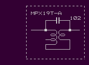
The MPX coil series of Toko, Inc. is a convenient coil that can be used for the color
usage when the connection method etc. are devised.
Well, please connect the experiment modulator of this matrix
type with VCO next time, it pursues the subject while seeing a final
characteristic etc. , and prepare VCO to which experiment performance can be output and do the following preparation.
Do you break out ?
Next Page /the experiment and see !?
FM stereo matrix generator introduction
document of yamamoto by WildCat FM |
| jumps to the top page. | returns on the previous page. | returns to the first page. |
2005/05/04 last modified on 2005/11/09
 |
 Bad example of signal
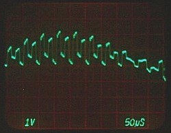 Bad example of signal
