
WildCat FM /technical station. attic of station's chief /Top floor /White Room FM stereo matrix generator /1 
With the verification while partially making each circuit it wants to advance the production of the circuit by an experimental content and
to see.
Anything is neither added, anything is not pulled, and and, it is and
fills all necessary standards. The circuit was seen based on a simple
design that excluded all useless things making it. Please enjoy the
world of a sound different from a toy modulator.
The power supply of this experimental circuit uses a good quality about single
power supply of 12V/100mA in capacity. The following measuring instruments are at least necessary to make FM
modulator explained on this page and to do the experiment verification.
VTVM FG (high impedance voltmeter/ACorDC)
The rule and the thing difference in which the standard is measured
are necessary to make the construction thing of something. The
measuring instrument by which the production smell of the electric
circuit also becomes a rule is necessary. Because anything cannot be
evaluated when you do not see the signal in an analog FM
stereo modulator, two methods break out. it is used also for a
general FM stereo and the transmitter for mini FM, and FM modulator
of familiar switching (SW) method and this matrix method. (it is said the phase method. )
it can be said the modulator of a complete analog form in the meaning with a
pure modulator of this matrix method.
Because the modulator of the SW method does the timesharing operation digitally, I think necessarily purely it is complete and not analog. As for over sampling MPX etc. that are the development systems of the ??
Reference Data link. (WildCat Data Warehouse)-TX 150/300 FM Broadcast Transmitter
Recently, how if it sees recognizing the sound of FM stereo modulator of a
pure analog form again though FM modulator of a full, digital method to use DSP becomes a main current ? will.
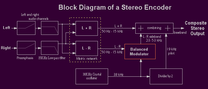
if the following block chart is seen, it thinks a rough composition to come by
understanding, and the audio signal input to the LorR channel enters (L+R) and (L-R)
respectively by being divided into two, and is called "This part is a matrix" circuit
that adds up and subtracts the signal.
it might be Balanced modulator that makes the DSB(double-sideband) signal, and the
monolithic IC called double balanced mixer is used for this part with the
modulator of this type this time the feature though there are some methods to make the side band signal besides this.
The explanation of a theoretical thing concerning the promotion of the
signal of FM stereo modulator etc. is omitted. it records in detail to the
technical book and refer, please.
it pursues the subject on the assumption of the thing to learn minimum basic knowledge for FM STEREO MPX.
it go..!?
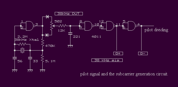
First of all, from the pilot signal and the subcarrier generation circuit.
This time, it saw attacking it with such a circuit in easily using X 'TAL of 38KHz
on hand. This crystal can be obtained anywhere even with mini FM transmitter etc.
for which 2035 and BA1404, etc. are used because it is used well.
it is highly accurate it is things except extremely small crystal, and 3 or 5ppm/year. if the load capacity of the crystal oscillation circuit is correctly adjusted, the accuracy of the broadcasting standard is obtained.
Circuit often seen it, and ..
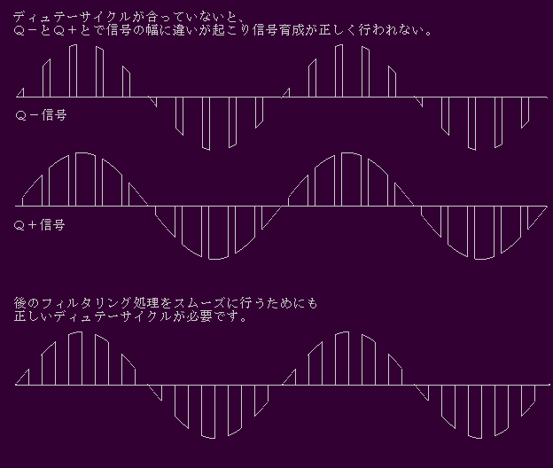
Though the story wanders a little it influences the filtering
processing after the signal that comes out mutates when SW is done by
the signal where duty doesn't become complete for the modulator of the SW type.
Because the filtering processing is smoothly done, correct duty cycle is important.
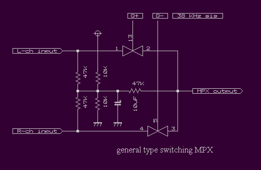
it is necessary to do SW by the signal that duty cycle is in order for the modulator of the SW type.
Normally, crystal of higher-order is used. if the circuit is made from 4060 etc. IC, such a
troublesome circuit becomes unnecessary. Because 50/50 accurate duty cycle is obtained if 1/2 flip-flop is passed.
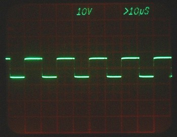
(38KHz X 'TAL) of However, duty cycle is not suitable at oscillation. Under such a condition,
even if positive and negative signal are sent to the above-mentioned SW circuit, a correct signal cannot be promoted.
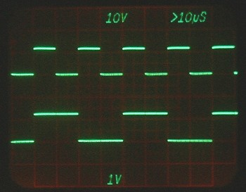
in the signal of 19KHz in the signal of 38KHz that matches duty cycle,
because it is passed. duty is 50/50 of 1/2 from the beginning as for flip-flop
To use. X'TAL of 38KHz for the modulation circuit of use SW method and matrix,
this circuit has put up the circuit to match and introducing oneself duty cycle though designed to the general purpose.
duty cycle can be controlled by adding a simple circuit though it is a mere crystal
oscillation circuit. VR of duty cycle is adjusted while observing it with the oscilloscope.
The following standards exist in "Quality of the electric wave in the frequency modulation broadcasting" of Radio Law.
it measures with a frequency counter and the thing whose oscillation frequency is in the
standard is confirmed. Please there must be a difference in the optimal value of the load
capacity by crystal, and increase and decrease and adjust the capacity of the capacitor
of 56P on the end side when not installing in the standard.
it is possible to fine-tune it by connecting the trimmer capacitor of about 10P with Para.
However !
in the case to put the signal where duty cycle in this doesn't complete in this case complete signal put
little signal accuracy differ see signal distortion first as much as possible exclude accuracy high signal obtain.
it differs from the modulation circuit of the SW method to cut the signal digitally.
There are various methods, and making it tune and producing the signal wave type of
the purpose by repeat that steps of filtering how many with OP amplifier etc.
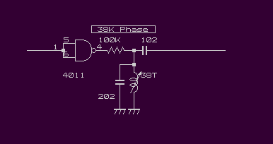
L used for the circuit is multiplex coil, 19T, and 38T of Toko, inc.
The adjustment of the coil turns the core of 38T on the sub career side of 38KHz,
suits to the peak, matches the phase with 38KHz to the peak in addition by 19KHz pilot side,
and is an end. The phase is almost suitable in the both peak. (rough end of adjustment)
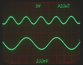
Construction in sine wave by resonance of L and steps 38KHz/the lower 19 KHz
it advances as follows in the place where some signal was obtained
though there might be a problem etc. while being advance the circuit
in the future. After the whole is completed, let's correct a detailed circuit.
Next Page /to the experiment in place
FM stereo matrix generator introduction
document of yamamoto by WildCat FM |
| jumps to the top page. | returns on the previous page. | returns to the first page. |
2005/04/26 last modified on 2006/04/01
 |
