
WildCat FM /technical station. attic of station's chief /Top floor /White Room FM stereo matrix generator /2 
Production is advanced with Step by step
with the verification of each
circuit. If operation cannot be understood, the adjustment that makes the
best use of the performance even if the circuit can be done cannot be done.
Let's study the operation of the circuit and proceed to the next step.
Production of L-R, L+R circuit, and Balanced modulator circuit
Well,it hangs in the production of the center part of the modulator
in the place where the subcarrier generation circuit can have been done.
This circuit : to Balanced modulator it saw by using double balanced mixer a IC TI/SN76514.
IC is thought that the AM modulation circuit is made before and exists in "Manuke" why though is a thing stocked in some measure, and the data seat of IC is lost, and you do not have the material that can be offered this.
sent to Balanced modulator for modulator of matrix method The signal of L-R is a general circuit to
synthesize by usually using the input of +/- the OP amplifier and has been synthesized by using
the input of +/- the OP amplifier even if the circuit of various modulators is seen. The
modulator circuit of famous orban optimod 8100 has been
synthesized with the OP amplifier in the sound processor.
This circuit is in an initial design phase with the OP amplifier. A synthetic circuit
of the signal of L-R existed.
The thing in which the function that was able to be done was provided was deleted
simultaneously with the DSB modulation, and it began to be and deleted a synthetic
circuit of the L-R signal from the circuit from an internal equivalent circuit to
looking the deletion of SN76514 that was double balanced mixer (DBM) of the synthesis of
the signal of L-R with the OP amplifier when seeing examining an internal equivalent
circuit of SN76514 again.
Actually, it is a design that has not disappeared the circuit of L-R and is absorbed to an internal equivalent circuit of SN76514. This circuit can be applied to the circuit of the stereo modulator of the matrix type that uses double balanced mixer /LM1396 LM1496 LM1596 uA796 N5596 NJM1496 etc. other than SN76514. When SN76514 cannot be obtained, it is possible to substitute it for this circuit with above-mentioned IC though it is natural.
There is a large advantage by absorbing the L-R circuit to the equivalent circuit in double balanced mixer
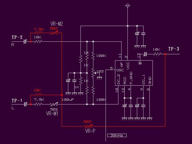
First of all, the subcarrier signal of 38KHz is injected from the subcarrier generation circuit into 5- pin of double balanced mixer SN76514.
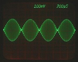
The signal generated in TP-3 of the injection of the subcarrier signal is
observed by using the oscilloscope or VTVM, and career suppression is done with VR-S1 and suppressed.
[TEST-1]
L-R operation is normally done, the voice signal in phase suppression can be secured by -60 dB more.
When you can confirm the thing that the DSB signal is promoted The
circuit that synthesizes the L+R signal is added and the stereo/MPX signal is generated in TP-3.
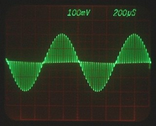
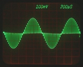
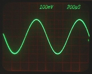
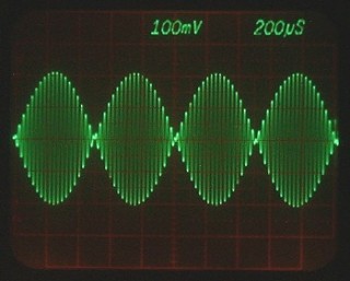
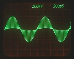
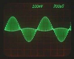
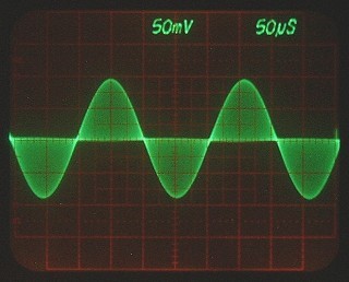
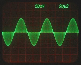
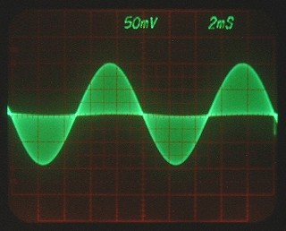
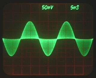
When VR-P is adjusted by injecting signal (AF_signal) into TP-1(L-ch)
or TP-2(R-ch), the following MPX signals are synthesized.
[CHECK-4]
The base of a high Separation characteristic is obtained by the balance and
adjusting the circuit. When you do not obtain the shape of waves of the above-
mentioned image by the confirmed signal
Because the balance is not suitable or the circuit doesn't function normally,
it is necessary to readjust.
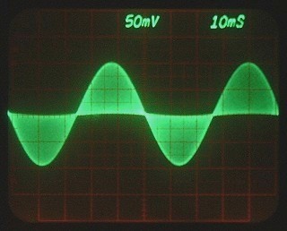
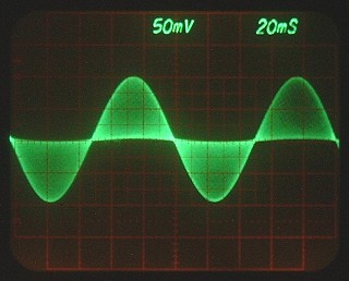
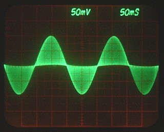
The correction of the following signals is adjusted with VR-M1/VR-M2 in CHECK-2 and CHECK-3.
(LorR /each channel can do an independent adjustment. )
The above-mentioned signal image is bad. Each signal also
obtains neither limit nor a straight stereo Separation characteristic
that the center line doesn't become a straight line.
The case of a general modulator of 50Hz or less,
especially the low region signal and the high region signal of 10KHz or more fall into
disorder, and the Separation characteristic of each frequency is deteriorated.
experimental circuit of synthetic signal (measurement environment-3)
5KHz/AF_signal/L-ch signal
10KHz/AF_signal/L-ch signal
15KHz/AF_signal/L-ch signal
Characteristic of low region signal
100Hz/AF_signal/L-ch signal
50Hz/AF_signal/L-ch signal
20Hz/AF_signal/L-ch signal
10Hz/AF_signal/L-ch signal
5Hz/AF_signal/L-ch signal
The circuit enters after this back and forth, and it changes to VCO slightly
though the signal wave form has been slightly distorted still by the connected
state. When connected with VCO, a final adjustment will be severely done. A
final evaluation is decided with everything went out over the air.
Was a basic part of FM modulator able to be understood though it became a considerably
heavy content?
Next Page /Do you advance to the following experiment circuit ?
FM stereo matrix generator introduction
document of yamamoto by WildCat FM |
| jumps to the top page. | returns on the previous page. | returns to the first page. |
LastUpdate. 2005/04/30
 |


