
WildCat FM /technical station. attic of station's chief /Top floor /White Room FM stereo matrix generator /4 
Production is advanced with Step by step
with the verification of each circuit.
The following measuring instruments are necessary to verify FM modulator
explained on this page experimenting.
Connection to VCO/exciters and phase of pilot signal
The sound is emitted though it depends on the modulation sensitivity of
VCO if the last circuit operates well if it connects it with exciters.
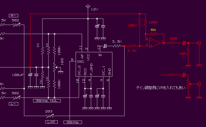
Let's put the buffer with the OP amplifier temporarily as follows and connect it with VCO.
Sensitivity is different because of VCO and adjust for an appropriate
modulation level to go out, please. When the modulation level doesn't
go up, you may change return resistance RA of the OP amplifier to a
suitable value, adjust for an appropriate modulation level to go out, and put VR etc.
Well, because the modulation level changes depending on the frequency when
there is Pre-emphasis up to the end of a general test and the measurement, the
capacitor of the emphasis is removed from the circuit though experiment of
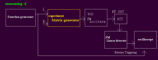
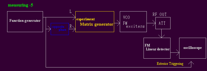
this time matrix generator is finally connected with VCO and it tests as shown in the figure below.
it modulates correctly in the synthesized MPX signal in the place where the
measurement environment was changed or it measures it.
Audio signal (AF_signal) of about 1KHz is put in experiment Herr/matrix generator,
and it sets it to about 50% while seeing the modulation level with a straight
line detector.
1KHz AF_signal /L ch signal of promotion image
When the shape of waves has mutated slightly by VCO(FM exciters), it readjusts
according to last time. When the signal cannot be correctly reproduced even if it
adjusts it though an accurate to some degree signal had come out in the last state,
it is necessary to correct VCO so that a correct modulation may hang or to change
it into VCO by which a straight modulation is multiplied because there is a problem in VCO.
it verifies it in each frequency when it can be adjusted that a
correct MPX signal comes out by the audio signal of 1KHz.
Especially, please put, test the audio signal of each frequency, and whether
neither the low region signal of 50Hz or less nor the high region signal of 10KHz
or more have mutated look. 10Hz
If there is no problem in each frequency like the above-mentioned
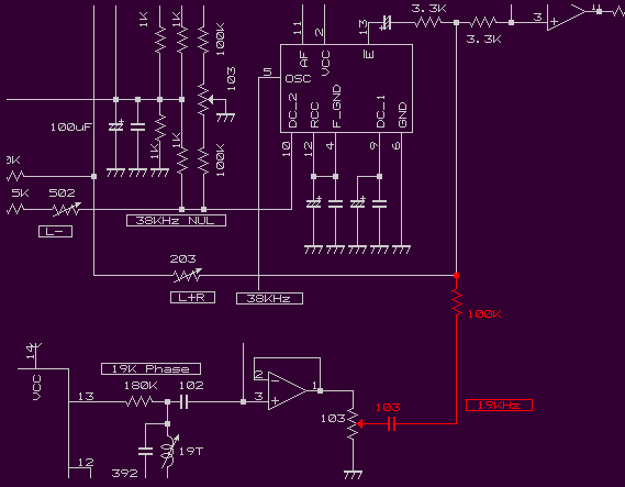
The circuit that does the pilot signal of 19KHz in MIX is added and the pilot signal is injected.
When the circuit can be added, the cooking stove of a straight line
detector is set and the level of the changing pilot signal is set to
8-10%) and several Frequency Deviation (6-7.5KHz) temporarily.
Whether the shape of waves of the pilot signal is distorted by the oscilloscope is confirmed.
When the pilot signal can be injected, it is necessary to phase it to the subcarrier of 38KHz.
Well, there is variously how to confirm the phase of the subcarrier and the pilot signal.
Both are only the extremely ways.
it explains by this way this time because the method of recording in the
manual of orban optimod 8100 is easy comparing it.
(Refer to 8100A1 Manual_Section_4/4 page. )
1KHz AF_signal/(SUB)/opposite phase signal is put in L and R channel of the voice
input like the following measurement environment, it observes with the oscilloscope,
the coil of 19KHz/19T is matched, and the center of the crossing point of the turning signal is matched.
The audio signal is confirmed, and when the coil is turned, the peak
value corrects the stop pilot signal level, and puts audio signal
(SUB) again and confirms the phase because the gap signal level changes slightly.
The settings were matched, reproduced, and seen as much as the image recorded in
the manual of orban.
it is a right measurement image to have expanded the crossing point of a left measurement image.
Because the phase is not suitable when it is the following, it is necessary to readjust.
At this point if the phase of the pilot signal with the subcarrier is suitable.
When it is a straight FM tuner, Separation of 50-55dB or more is sure to be obtained enough.
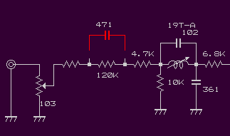
Please return based on the connection of the capacitor of Pre-emphasis
input the voice from the mixer, and enjoy even music.
The next experiment verifies the signal modulated by this modulator from the side of
the electric wave and examines the circuit.
Next Page /it advances to the following experiment
FM stereo matrix generator introduction
document of yamamoto by WildCat FM |
| jumps to the top page. | returns on the previous page. | returns to the first page. |
LastUpdate. 2005/05/07
 |
