
WildCat FM /technical station. What do you want to do with a toy of this "398" FM transmitter ? /TR-10RDX 
It is an external antenna, for the electric wave of TR-10RDX to fly far...Nyaa..!! Such a reality is not however sweet though it is a good thing that executes by thinking in the in one's own way. A tidy antenna is necessary so that a halfway thing may fly uselessness and the electric wave no matter what it does. Because it is quick to open the inside to draw out the output from TR-10RDX outside and to use an external antenna take out the output directly of the
base with the coaxial cable, I will see attacking it though it is an improvement for a moment.
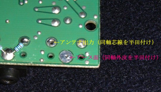
TR-10RDX is first dismantled and the antenna terminal is removed by using soldering iron. It removes while sequentially melting solder because there are three places where solder adheres. The thing removed to the riot cannot be done.
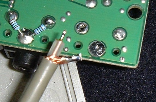
Please look at the photograph below. The point that connects the coaxial cable is shown.
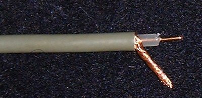
Next, please prepare the coaxial cable to take out the output. As for the cable for taking out, the thing of narrowing might be good because it solders directly with the base. The cable in the photograph in the under as a suitable example of length (10cm-15cm) title is 2.5D-2V because it only has to be able to take out the output.
Next, the hull and the wick line are separated. The union line of the hull is politely unpicked and brought together.
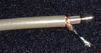
Next, solder is put on the hull and the wick line as a preparation to solder firmly.
Next, the wick line and the union line of the hull are trimmed beforehand
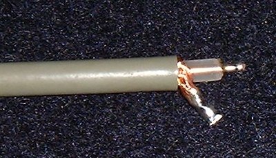
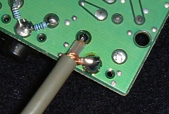
It trims correctly as shown in the photograph below. The position that is compared to photograph 2 and soldered is confirmed.
The trim, and the confirmation of the position is OK and is, and completion if it solders as it is.
Is it did make to good ?...Nyaa..!! The BNC connector etc. are put up to the same ax drawn out to connect it with the same ax of an external antenna and completion.
Is if a straight FM transmission antenna is used, the distance of a jump of the electric wave 100 times compared with the antenna of the attachment to TR-10RDX. It increases by a factor of 1000. Will it be terrible ?....an external antenna for the electric wave to fly too far ?...Nyaa.!!...
1. Power up TR-10RDX.
|
| jumps to the top page. | TR-10RDX menu page. | returns on the menu page. |
LastUpdate. 2005/09/20
 |

