WildCat FM /technical station.
Transmitter happily made
Let's output a beautiful electric wave/a basic part of a standard electric wave
What is the Ideal FM transmitter

It is a new project to enjoy the technology.
Transmitter KIT sold for mini FM is actually produced. It introduces it one by one on this page. I think that it serves as a reference from the beginner to the old-timer. Then, it goes to be going to buy KIT of the transmitter in the future.

Page next update to the enjoyment.


Does the oak and getting on mean and very does badness. mean whether to say if it carves it for the state as it is and as many as two years though the project in fiscal year 2002 should have started for the feeling ? No one cannot get on, and toy KIT spurn the feeling very much now certainly. A very rough-and-ready work of the omission does.. "Ideal FM transmitter" Bare then to changing into the theme and the record of the requested basic matter and merits in FM transmitter 'I will not explain the omission for you who hopes for the technology at the professional level. the content considerable Heavyweight though.

Please concretely narrow the content of the question on if there are an uncertain thing and a doubt for this page. A special technical staff of WildCat FM each will answer taking the responsibility.


transmission part (transmitter)= FM Exciters and stereo modulation Transmitter. machine FM stereo generater ....
so-called though it combines and it wants to expect calling FM transmitter = FM stereo Transmitter.

It might be correct that the fellow with a small output for Excite says FM stereo Exciters. !!

Large a chine leave the FM stereo Transmitter showing in a certain place for taking the shape and wanting expect saying? The small size is interesting the professional world because it becomes the machine of about 100W. ..(Wa

Introductory remarks and merits are excess. To the subject in ...

It becomes ..encounter.. standard before that quality of the lectric wave in the frequency modulation broadcasting) of , of a low limit of .... and refer on the tip of here, please.


"Ideal transmitter" first of all, from the requested matter to basic part where the electric wave is output


1.Thing that performance can be maintained by strongly extending over a long period of time to environmental change
It doesn't become a talk, and it be decided to the thing that a steady performance can be maintained under a severe condition even if it is low somewhat performance good only first that my performance is always thinking it is basic by hitting design a circuit good. Do not misunderstand a low performance because the thing that you are considering and the dimension are different even if it says.

If the spec cannot be maintained with the change of scene even if how much initial spec is good, it is Tsu no use. It thinks to the spec and it sees or the hoop changes with a public welfare machine that omits under all conditions for the professional machine and is steady to which the condition is limited as for the performance.

The aging of one year is being verified to the spec of the transmitter having it for me now.

In a certain place, it was taught that a professional spec was basically a thing said so.
It is at my hand, and as for the equipment, present that actually passes 20 years or more and a breakdown once are not and operate though were calle the equipment of a certain place where teaching was received 20 years though it operates every day at that time, too. It is made learning ability that years of 20 years or more pass, are renewed, and a genui terrible. There is actually no performance deterioration and it has been arriving now with a spec at that time maintained to complete.


2.Thing that clean, steady electric wave can be output
This is difficult though it says in short.

Then, from the starting point of the electric wave ...
The starting point of FM electric wave may have the thing that worsens even if "Changeable frequency oscillation machine" this VCO = does what kind of thing Yabai and after, and the becoming it thing breaks out absolutely and is profitable.

With OK if it oscillates temporarily in the broadcasting bandIt is the other side thought to obtain a steady frequency with PLL, a big mi sunderstanding, and if the idea is not renewed, a signal straight even if passing until what time is not obtained now.

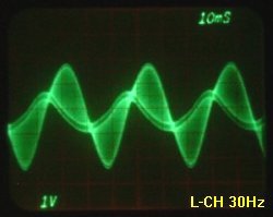
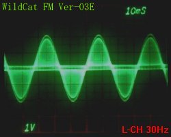
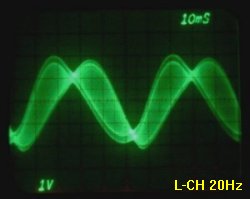
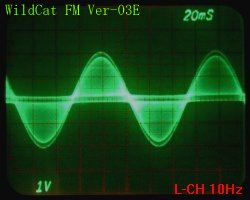
There is PLL for VCO to the end only in the auxiliary circuit.


Transmission (oscillation) frequency maintenance device(PLL . phase and lock loop)

The crystal oscillator that the stability level is said that it is high builds in, it exists, and the electric circuit that always observes the frequency of the crystal oscillator by which the comparator becomes the oscillation frequency and the standard of VCO and corrects the gap of the oscillation frequency automatically. Because the control at the phase level is done as theoretically as the name of PLL, a stability level that is the same as the crystal oscillator and high is obtained.

oscillation purity
the thing is not correctly transmitted to VCO even if information is put on a feculent signal. Let's understand

If the accuracy of a basic signal that transmits it even if a very clean audio signal is put (purity) is bad, the information is not accurately transmitted.

If those who say are done, can "gitta in the electric wave or wow flutter" be able to be understood a little?

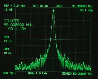
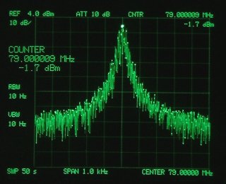
The oscillating signal is observed to blur slightly compared with strict Mi and a center frequency. Is it several degrees in the slight one? As for the bad 
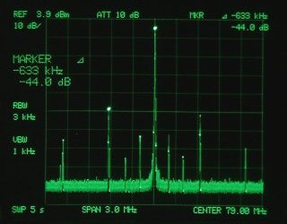
thing, the one blur can be confirmed to several KHz or more by about 10Hz. This in the faulty design of the circuit.

The many have caused this blur at high speed. 
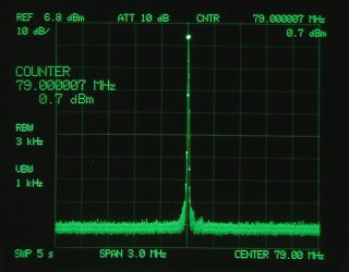
A center frequency as the mean value cannot confirm this minute blur to having in the measurement of the frequency counter as for the thing that the control of PLL twines because it is correctly displayed (As a mean value).

If the band is narrowed and confirmed with highly accurate Speana, it is confirmed that the skirt of the signal is Dobar and has extended. The transition of this slight phase is bad compared with S/ N of the electric wave (purity). have because of a certain kind of phase noise .

Do you transmit compared with actual S/N? Though it becomes an evaluation on the reception sideIt is possible to calculate twining S/ N by several maximum Frequency Deviation of the frequency modulation broadcasting (150KHz= 100% modulation ) compared with.
 

Extremely clean signal This signal in a standard signal of the high precision crystal oscillation machine. Accuracy is 1x10~10 it is a mastering signal of LABO. FM transmitter is 1x10~6 The signal ndiscriminately by minute disorder of VCO and the influence with PLL and the skirt of the electric wave has extended.
 

In the measuring span, it is 1000Hz(One grid of the frequency axis is 100Hz), and resolution (RBW.VBW) is 10Hz.

As for the signal in a right image, the signal purity is obviously deteriorated and it is understood that it is bad compared with S/N when comparing it with a left image (high precision crystal oscillation machine). As the signal of FM transmitter, this is Pure signal. The bad signal is ..this screen installing The measuring span ..might an integral dB it how many compared with S/N of the signal in the image in and the right is 1000Hz, and one grid is laughter 100Hz.
Do over there from see the measurement image and left by gooseflesh though it is thought that it derstands?

Moreover, the design of the loop filter of PLL badly by the control noise of PLL. It is modulated and the model that increases the phase noise with accelerating speed exists considerably in the inside, too. When the lock cooking stove of wide-ranging PLL is obtained, deterioration in the electric wave (purity) is not avoided by the control noise of PLL.

Moreover, the frequency floats when the time constant of the loop filter is lowered to avoid noising easily. To avoid this, the design of a complex loop filter by the advanced technique is needed.

I do not have meeting to our regret in an efficient transmitter that still completely clears this conflicting problem to which the advanced technique is turned on.
 

Cannot an ideal transmitter be able to suppressed a slight blur of the phase if it doesn't at least suppress it up to about 15 degrees because VCO of FM Exciter needs the frequency modulation signal with a wide cooking stove though the advanced technique is necessary?

To secure the frequency modulation signal with a wide cooking stove, VCO causes the problem of the floatage of the frequency, and sees a high equipment considerably. bad's? There is what sees 200Hz and moved gradually up and down.

This is a class of mere defective goods if it sees from the engineer who is taking one's life in one's own hands to the frequency accuracy. !! Around here?It cannot be said that the stability level of VCO is good if it is not a title by 30Hz or less.

It doesn't stabilize even if the numerical value of the digit of the frequency counter in the under is moves, and it passes until what time. The numerical value of XXX of three last digits always changes by 83.800XXX when it is bad thing. It actually confirms it with the transmitter at Community FM level.


There is a signal that changes to length though even here is a story on side.

AM modulation noise
There is saying in Radio Law to the item called the quality of the frequency modulation broadcasting electric wave, "Residual amplitude modulation noise". The change of the length of the electric wave because of the noise generated from VCO is restricted with -50 the dB or less.
The purity of the oscillation compared with S/N of the electric wave becomes a problem as previously described.

The purity of the oscillation is a problem.

The AM signal is from FM transmitter to going out it, and the problem even if it is a little.
It separately schedules it the explanation for the AM modulation noise.


"Minipara"
It is minute oscillations outside a basic frequency that it is a lot of in VCO of the faulty design.
A minute oscillation signal includes it besides a basic wave, and a lot of phenomena that are include and VCO includes VCO that can be observed a basic frequency though it oscillates. I am calling this bad oscillation phenomenon Minipara. It is seen a lot in the toy transmitter that the garage factory of < without such equipment makes though an abnormal oscillation outside the purpose can be confirmed if it confirms it with a measuring instrument. Unusually, the thing that the professional machine can overlooked breaks out, and the case that becomes an electric wave trouble that cannot be evaded when staying up in the vicinity of a basic wave exists.

When listening with FM tuner, a slight electric wave can not be received by various frequencies in intraband in happening because an at close range strong electric wave is received.

 
Extremely clean signal to which minute oscillation signal etc. are not observed VCO that can observe a lot of oscillation signals minute besides basic wave.
 

in the measuring span, 3MHz (center right 79.0MHz/left end 77.5MHz/edge 80.5MHz) resolution is 3KHz

As for a right image, a lot of signals can be confirmed to surroundings of a basic wave (Intraband is only garbage). The electric wave trouble cannot be evaded because there are no prevention ways in the bandpass filter and the low passing filter when existing near intraband and a basic wave because this garbage signal of 79MHz-633KHz=78.367MHz that there is a strong signal in about -633KHz for a basic wave is amplified as it is.

Moreover, by the mutual interference when this minute oscillation exists near a basic wave It causes to be generated an unpleasant beat sound the causing reception ..interference beat of the stereo and the pilot signal.. sound.

This garbage signal might happen because of signal Leak of the loop filter of PLL, and appears to integral multiples of the comparison frequency in this case in rows. If PLL is separated, it is possible Leak spurious by faulty design of PLL it is the one by VCO to identify it.

so-called Para oscillation are "It is a phenomenon (abnormal oscillation) that oscillates disorder it as for all the frequencies. "

If the oscillation signal of VCO doesn't oscillate Pure signal from the beginning I want to get it from an original signal of an ideal transmitter driving in the of can use thing to the head once now. What you may do, and the becoming it thing is breaks out absolutely and profitable in the starting point of the electric wave as having explained by us useless even if VCO and this do what kind of thing bad and after.

The thing that the result your should would being better to design a circuit that is newer to tinker halfway VCO is obtained is more abundant.


3.The modulation without the distortion and the straight line are good things.

The starting point of FM modulation is a changeable oscillation machine, and according to "Changeable frequency oscillation machine VCO =" and the audio signal as for the frequency. Naturally, if the oscillation frequency cannot be accurately changed to the audio signal, the signal is distorted.

The electric wave of FM makes the oscillation frequency change up and down according to "FM=Frequency Modulation = frequency modulation" voice signal as its name suggests and transmits the voice.

Problem of PLL given to VCO
The contradiction said that it cannot accurately change the oscillation frequency to the audio signal is caused, and it happens dynamically in the low frequency region of the audio signal of especially 100Hz or less because PLL perceives the gap of the frequency when the transition of the oscillation frequency happens because of the audio signal and the correction is put.

Because the oscillation frequency cannot be accurately changed, the signal is distorted. An inferior thing is 50Hz? though this has the problem in the design of the loop filter of PLL with the modulation circuit of VCO in many cases. The input of the audio signal of about 200Hz collapses by receiving the obstruction of the control signal of PLL and no stop of the shape of waves of the audio signal of the prototype.

Tone quality becomes and becomes a story before saying because it cannot correctly modulate the audio signal when VCO is very much imperfect with an excellent, efficient modulation machine.

Engineers of a certain famous modulation machine manufacturer have seeing the thing the plain description to the manual to lose his/her temper considerably because the performance of the in-house product cannot be made the best use of by Exciters for the professional because a lot of things with a bad low region characteristic exist when adhering to this matter. Then, Exciters is developed by itself and in the furnace though it thinks Other areas cannot be violated because it comes near to a union for the United States and it is protected. Do ahead of that with Exciters and stereo generator though it is not in an easy story because a technical genre is extremely different?

If an efficient modulation machine is used, VCO that the low region characteristic is good was installed, and if Exciters is not used, an efficient modulation machine becomes a mere ornamentation because there are no 100% life skein ..the performance.., too.

10Hz? temporarily though it doesn't become a talk in the equipment that the signal doesn't pass ahead of that. oscilloscope ties, is confirmed to a straight line detector, and whether the signal of about 20Hz is input to L or R channel and whether it collapses and the signal exists I will see.

 
that receives obstruction of
control signal of PLL and mutates
Signal of normal
The problem before tone quality because the signal has already collapsed Do you speak seeing the comparison of these signals, the sound good or badness?

Because the signal already has collapsed, object of the comparison.. think that it is a place honest.

The view of the oscilloscope screen though thought that it is possible to understand

enough to the understanding of the view of the measuring instrument. Look at the last image, it is displayed as 50mS to display TIME.DEV to upper right, and is displayed time that the time axis of this person mass of which it thinks (ten masses in length and breadth) when the lattice (grid) is seen in length and breadth sideways does the sweep though this is not seen easily on the screen where the time axis is displayed. Therefore, the thing that includes the thing said the observation by 2+1/2 waves every 0.5 seconds that become 0.5 seconds in the signal of 5Hz comes by the confirmation at time for 50mS to do the sweep from the left of the screen to the right. The frequency of the signal that does other screens in this manner and is displayed can be confirmed.

the influence on the signal grows in a frequency that is lower as understood.

It is necessary to note it because the sound not only becomes unstable if the influence when the obstruction is received goes out with PLL in this manner the audio signal and the signal below the coming frequency is not cut with the filter etc. but also the stability level of the transmitted electric wave will be lost though tone quality becomes a story before saying because the audio signal is correct and it cannot reproduce it.
 

In the transmitter of the image on the left, if the frequency less than it is not cut with the filter because about 70Hz is a limit, can it be simply guessed that the adverse effect goes out to tone quality from the signal?.


Because the restriction of the upper bound frequency has been received by the Parot audio signal of FM stereo signal, it is large in a basic quality and influences it to emit a good sound whether the signal with a clean without the distortion low frequency band region being able to be reproduced. Recently Europe frequency modulation broadcasting equipment audio signal low frequency band region how reproduce say respect value circuit design equipment a lot see technology shop arrive all same anyway low frequency signal high frequency signal multiply region signa distort all sound become impure region signal distort powerful enemy thing become By the way, latest FM Exciters of Europe has sales of the signal of 10Hz coming by reproduction.

To transmit because of a good sound in FM stereo, the performance of VCO is greatly related.


Starting point 1 of the frequency modulation broadcasting wave is a signal that VCO oscillates. (calling commonly career signal, and main signal carrier)When whether it is called the career
signal is said why, it is a thing of the signal that simply carries the thing. The signal cannot fall into disorder or be impure and information be transmitted accurately.

Starting point 2 of the frequency modulation broadcasting wave is a subcareer signal (subcarrier) that transmits the stereo voice signal.
The electric wave of the frequency modulation broadcasting has extremely delicate stereo voice information called a subcarrier in voice information that put voice information on a main signal carrier and was put by a main signal carrier. If the subcarrier has fallen into disorder though there is a main signal carrier clean, information is missed and cannot be transmitted. (The monkey understands. )A good sound is reproduced only after all of the information are accurately transmitted by the listener. A small turtle has gotten on on a simple story and mother turtle and final information has gotten on on that. Which turtle transmits and information is not transmitted in correctly.

In this,, Understand.

A main signal carrier is a signal that oscillates in the frequency modulation broadcasting band . As the example, 80MHz TOKYO-FM etc.(signal of electric wave)
38KHz in the subcareer signal that transmits the stereo voice signal with the subcarrier. (It is suppressed at a no sound standing up with the audio signal by an intermediate signal of the electric wave and the sound without the audio signal. )

To synchronize the subcareer signal on the reception side, a standard signal and the pilot signal is 19KHz . (signal at a position extremely near the audio signal. )

20Hz? voice information (audio signal) when FM stereo broadcasting is generalIt is a range of the frequency in the ear of 15KHz where I hear (It is a signal of the hearing sound in man's ear).


When the site is updated next time, the chapter of FM modulation machine is scheduled.


Supplementation
In the above-mentioned explanationThe point of the matter to which the harmonic component of the electric wave and the explanation for spurious were not performed was received. It wants to explain the harmonic component and spurious somewhat when the site will be updated next time and to see though it pursues the subject by the viewpoint said that it is natural that the harmonic component and spurious are removing it made.

Without omitting it as much as possible explanation It is basic of the page.
Opinion,Impression, Please send the content and the question that it wants you to explain.


What is the Ideal FM transmitter
What is the Quality of electric wave
a basic part of a standard electric wave /Pre-emphasis


jumps to the top page. returns on the previous page.  

 
2002/01/04/ last modified on 2005/10/10