

WildCat FM /technical station.
Coaxial cable Impedance Transformer for Dipole Antenna

Dipole Antenna..
that Mystery
Being able to call basic during the basis of the antenna is a dipole antenna.
Because the structure is also simple, every one degree seems for the produced thing to exist.
However, was the expected performance obtained?
I think that figures of the dipole antenna seen well are the following things.
Even this?it functions and it does by one respondent until obtaining a theoretical performance and not existing...it mystery
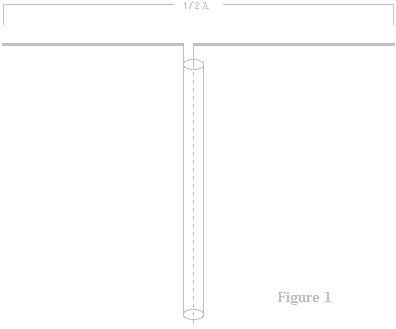 |
Figure 1
1/2 wavelength dipole antenna basic this
it is figure that records in the textbook related to the wireless and is going out anywhere famous.
The calculation type of the element length of it and the antenna
[300(m) / frequency (MHz)] / (m)=2 of antennas in length
By the way, the antenna is approved by 1/2 wavelength because of impedance and the voltage distribution of the feeding power point, it doesn't approve as an antenna in 1 wavelength and 1/4 wavelength, ....it is learning.??!!
|
However, this is a big mistake in use actually.
A dipole antenna original, basic Figure 1. then performance doesn't go out.
Well, it is that enters an unknown area though it doesn't know whether to be said it is taboo here.
Well, where will big mistake? Recording a wrong thing in the textbook. Possible ?
The textbook doesn't think about the thing that this antenna is actually used because it merely explains a theoretical thing.
it is strange for a moment though it cannot know be theoretically good in it. !!

Well, the element of the dipole antenna is actually the aluminum pipe or copper a pipe.
it is a copper wire etc. and a simple structure. Figure 2 on
In the impedance of the feeding power point, theoretical seem to be 72R title? ...Do not I know well either?
The coaxial cable of 75R or 50R is connected there. it must be unquestionable though Mis matting somewhat is caused.
it uses as everyone thinks so and there is not a doubted thing and something strange. either.
Looking at feeding power point of Figure 2, and ?. again.and it will mistake it greatly. already noticed you that the feeling is good!!
dipole antenna , pitfall of hell, and ultimate Mismatting
it was so, and, therefore, VSWR did not fall though how much element length was adjusted.
Because the element of the dipole antenna is symmetric, both feeding power point becomes a hot end.
Though the feeding power point of the dipole antenna is equilibrium (balance) when it explains plainly
Because it is not equilibrium (unbalance), the coaxial cable correctly matches the same impedance either.
in audio, the sound in which you may thrust it in the equipment of the balance input the signal of the unbalance is not emitted either.
if equilibrium (balance) connection is not done, the dipole antenna cannot correctly supply the electric power.
it is a story that frightens and is scary because the thing that do not do even the audio circuit is done with the high frequency circuit. !!
Most people do not notice Mismatting of this big mistake.
The electric power more than the half was discharged from not the antenna but the coaxial cable.

Correct feeding power method to dipole antenna
if a correct way is done if the mistake is understood, it is ..performance the dipole antenna original... (Hi
Impedance Transformer couple 1 is necessary to convert no equilibrium of the coaxial cable into equilibrium.
How to make Impedance Transformer couple 1 introduces the thing the use of the most general coaxial cable though it is ..various...
There is hardly the same ax's tying directly to the element like the antenna of the installation of the professional (Figure 1).
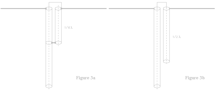
it is a thing that Impedance Transformer in Figure 3 above is handled well.
There is a necessity stored in the metal pipe etc. when setting it up because this coaxial Impedance Transformer receives the influence from the outside.
Calculation of element length of realistic antenna
Element length of 1/2 wavelength dipole antenna..??
[300(m) / frequency (MHz)] / (m) =2 of antennas in length
When the element length is decided by the above-mentioned calculation type seen anywhere often, 100% frequency is not suitable....niyaaaa!!
The tune frequency is low like 3 to 5MHz, and measuring it with 80MHz belt.
This calculation is approved only in space though the expression is not a mistake. !?
if the shortening rate to the permittivity is not put, the tune frequency is not suitable because air exists on the earth.
The shortening rate is (0.94-0.95) title that changes depending on the condition.(0.94667)
Because Half-wave is basic of the dipole antenna
The length of the element tuned to the frequency by 300 /(frequency) /2 * (shortening rate) is requested.
for 88MHz because of feeling by 300 / 88 / 2 * 0.95=1.619. it becomes the length of about 1m61cm
85m/m will be also different.!!
 About the shortening rate
The phenomenon of the physics length of the antenna element shortening by the permittivity in air on the earth is called a shortening rate. (Roughly though it differs for a moment. )
The permittivity in air is almost 0. There is no shortening rate needing because there is no air in space division 95th place.
The shortening rate is 0 with there nothing in surroundings, too . In addition, when the wall or the tree exists near though it is 95th place, it grows.
Therefore, only when the antenna is set up on an ideal condition, the physics length of the antenna element obtained because of this calculation is an effective numerical value.
How of the electric wave for the flight changes because the condition changes only into person's wandering about the vicinity.
Because the physics length of the antenna element changes greatly when the obstruction medium breaks out within the range of wavelength of the antenna set up, the adjustment put together on the condition is needed.
Therefore, the flight of the electric wave worsens because the antenna doesn't function effectively as long as the adjustment matched to the condition is not done even if is calculating made.

Coaxial Impedance Transformer's calculation of cable length
By shortening of the physics length of the antenna element by air
There is a light tray shortening rate also in the coaxial cable.
Do though it is thought that it knows because this has gone out when something
the catalog data of the coaxial cable is seen?
The shortening rate is 67% for 8D-2W and 5D-2W of The Fujikura Cable Works that I often use.
In the data of The Fujikura Cable Works, these shortening rates are written as 67%.
Fujikura's cable had only the error margin of 30cm or less every 20m for accuracy high 8D-2W in our measurement.
it drinks and coaxial Balin and Uilkinson, etc. function in the calculation value by no adjustment in cutting one in the length of the cable.
Because the shortening rate of 8D-2W and 5D-2W cable is 67%.
for Half-wave in 88MHz because of feeling by 300/88/2*0.67=1.14205. it becomes the coaxial cable of the length of about 1m14cm.
Even if U Balin and Uilkinson, etc. are made without knowing the shortening rate of this coaxial cable, the frequency already.
Because it flies to the day after tomorrow and is not tuned, it becomes a dysfunction
For the coaxial cable though the antenna element is a gap like 3-5MHz
Because the shortening rate is large, it becomes a dysfunction by Mage.... Shortening rate 67%
Because the insulator is not air and plastic for the same ax, the shortening rate grows.
The insulator decreases and the shortening rate has decreased as for the FSA cable etc. of the foam system.
(Please confirm the data of the cable used. )
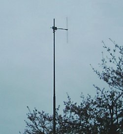 |
Half-wave Dipole antenna actually set up
(vertical polarized electromagnetic radiation)
Coaxial Impedance Transformer's is stored in the metal pipe in the horizontal part.
|

Feeding power method of Coreloadng of Coaxial Impedance Transforme
The same ax is Coreloadng by Coaxial Impedance Transformer's another way and there is a method of making Transformer wideband....Figure 4
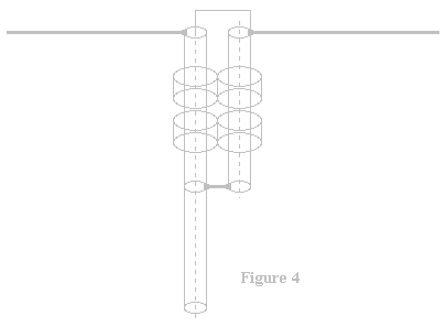 
The upper bound of the tune frequency band region doesn't change if strapping Toroidal core is put in a Impedance Transformer coaxial cable part. Thing to shorten the same coaxial cable comes because the lower bound falls.
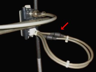 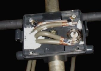
Because the coaxial cable can be shortened, it is possible to make it to becoming of it the difficulty to receive the influence of the outside like the loop like U Balin.
The core of Balin in the photograph can shorten the cable by putting in 3-4, and is ideal because of reserves though enters only a couple.
VSWR of this dipole antenna secures 1.1 or less.

The dipole antenna is correct and it is function unexpectedly difficult...
Especially, please give to me minding because Balin couple 1 is difficult.
I difficulty thing use before as a plain dipole antenna is straight.
the folded-dipole antenna was used because it had known.
Because U Balin's couple 4 treatment is easier than Balin couple 1. !!(Hi
| 